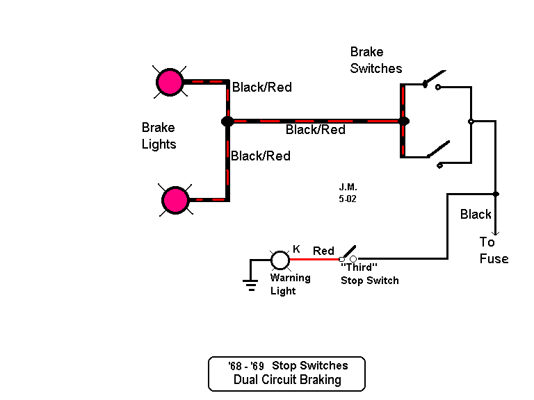
Understanding the Simple Brake Light Wiring Diagram is crucial for anyone working on automotive electrical systems. This diagram provides a detailed overview of how the brake lights are wired in a vehicle, allowing mechanics to troubleshoot, repair, or modify the system effectively.
Importance of Simple Brake Light Wiring Diagram
Simple Brake Light Wiring Diagram are essential for the following reasons:
- Helps identify the components involved in the brake light system
- Shows the connections between the components
- Guides in understanding the flow of electricity in the system
Reading and Interpreting Simple Brake Light Wiring Diagram
To read and interpret a Simple Brake Light Wiring Diagram effectively, follow these steps:
- Identify the key components such as brake light switch, fuse, bulbs, and wiring connections.
- Understand the symbols and colors used in the diagram to represent different components.
- Follow the flow of electricity from the power source to the brake lights to troubleshoot any issues.
Using Simple Brake Light Wiring Diagram for Troubleshooting
Simple Brake Light Wiring Diagram can be used for troubleshooting electrical problems in the brake light system by:
- Checking for continuity in the wiring connections
- Testing components like the brake light switch and bulbs for functionality
- Identifying any short circuits or open circuits in the system
Safety Tips for Working with Simple Brake Light Wiring Diagram
When working with electrical systems and using wiring diagrams, it is essential to prioritize safety. Follow these safety tips and best practices:
- Disconnect the vehicle’s battery before working on any electrical components.
- Use insulated tools to prevent electric shock.
- Avoid working on the wiring system in wet or damp conditions.
- Double-check all connections and wiring before reassembling the system.
Simple Brake Light Wiring Diagram
Basic Brake Light Switch Wiring Diagram Collection

How To Replace Brake Light Switch | Shelly Lighting

Brake Light Wiring Diagram

Speedy Jim's Home Page, Aircooled Electrical Hints

brake light wiring diagram

Brake Lights Wiring Diagram – Cadician's Blog
