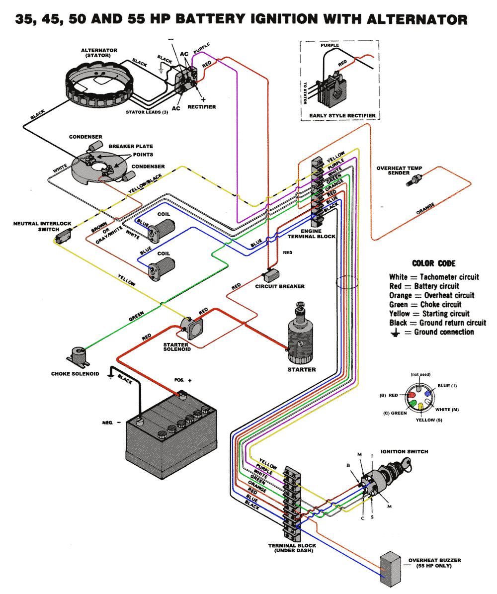
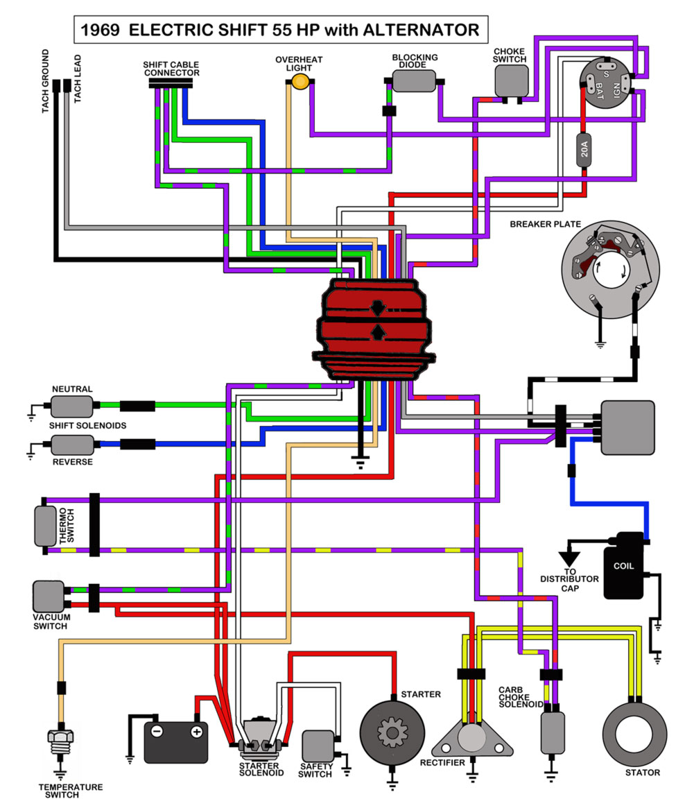
Johnson wiring diagrams are essential tools for anyone working on electrical systems in a Johnson outboard motor. These diagrams provide a visual representation of the electrical connections within the motor, helping mechanics and DIY enthusiasts alike understand how the various components are wired together.
Why Johnson Wiring Diagrams are Essential
Johnson wiring diagrams are essential for several reasons:
- They help identify the location of electrical components within the motor.
- They show the connections between different components, helping troubleshoot electrical issues.
- They provide a roadmap for proper wiring when installing new components or making repairs.
How to Read and Interpret Johnson Wiring Diagrams
Reading and interpreting Johnson wiring diagrams may seem daunting at first, but with practice, it becomes easier. Here are some tips to help you understand these diagrams:
- Start by familiarizing yourself with the symbols used in the diagram. Each symbol represents a specific electrical component or connection.
- Follow the flow of the diagram from the power source to the various components. This will help you understand how electricity flows through the system.
- Pay attention to the color-coding of wires in the diagram. This will help you identify the correct wires when working on the motor.
Using Johnson Wiring Diagrams for Troubleshooting
Johnson wiring diagrams are invaluable when troubleshooting electrical problems in an outboard motor. Here’s how you can use these diagrams effectively:
- Identify the specific issue you are experiencing and locate the relevant section of the wiring diagram.
- Check for loose connections, damaged wires, or faulty components based on the diagram.
- Use a multimeter to test the continuity of wires and components to pinpoint the source of the problem.
Importance of Safety
Working with electrical systems can be dangerous, so it’s crucial to prioritize safety when using Johnson wiring diagrams. Here are some safety tips to keep in mind:
- Always disconnect the battery before working on the electrical system to prevent electric shock.
- Wear insulated gloves and eye protection when handling electrical components to protect yourself from injury.
- Follow proper wiring practices outlined in the Johnson wiring diagram to prevent short circuits or other electrical hazards.
Johnson Wiring Diagram
Johnson Wiring Diagram 1998

50 Hp Johnson Wiring Diagram

Johnson 115 V4 Wiring Diagram – Wiring Diagram

70 Hp Johnson 1988 Wiring To Tachometer Etc Diagram

Wiring Diagram For Johnson Outboard Motor – Collection – Wiring Diagram

2 Stroke Johnson Outboard Wiring Diagram Pdf – Wiring Harness Diagram
