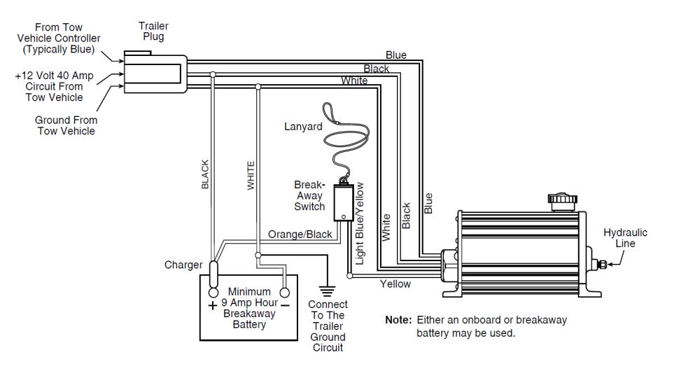
Electric Brake Wiring Diagrams are crucial tools for anyone working with electric brake systems in vehicles. These diagrams provide a visual representation of the electrical connections and components involved in the braking system, helping mechanics and technicians understand how the system is wired and how it functions.
Why Electric Brake Wiring Diagrams are Essential
Electric Brake Wiring Diagrams are essential for several reasons:
- They help ensure proper installation of electric brake systems.
- They assist in diagnosing and troubleshooting electrical issues.
- They provide a clear understanding of the electrical connections in the system.
Reading and Interpreting Electric Brake Wiring Diagrams
When reading and interpreting Electric Brake Wiring Diagrams, it is important to:
- Identify key components such as brake controllers, brake magnets, and brake assemblies.
- Follow the color-coding and symbols used in the diagram to understand the connections.
- Pay attention to the flow of electricity through the system to diagnose potential issues.
Using Electric Brake Wiring Diagrams for Troubleshooting
Electric Brake Wiring Diagrams can be used effectively for troubleshooting electrical problems by:
- Checking for continuity and resistance in the electrical connections.
- Identifying potential short circuits or open circuits in the wiring.
- Verifying the correct voltage levels at various points in the system.
Safety Tips for Working with Electric Brake Wiring Diagrams
When working with electric brake systems and using wiring diagrams, it is crucial to prioritize safety. Follow these safety tips and best practices:
- Always disconnect the power source before working on the electrical system.
- Use insulated tools to prevent electrical shocks.
- Avoid working in wet or damp conditions to prevent electrical hazards.
- Double-check all connections and wiring before testing the system.
Electric Brake Wiring Diagram
Electric Trailer Brake Wiring Schematic – Fannie Top

Demystifying the Electric Brake Controller Wiring Diagram: A Step-by

Electric Trailer Brakes Wiring Schematic

Dexter Electric Brake Wiring Recommendations
Electric Trailer Brake Wiring Diagram
Electric Brake Wiring Diagram
