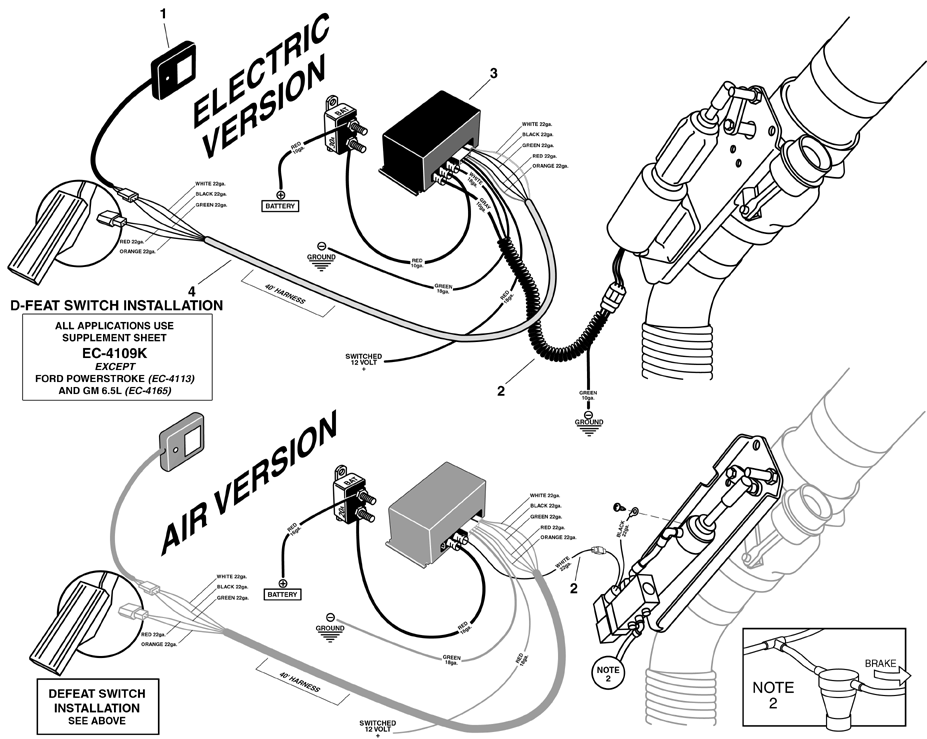
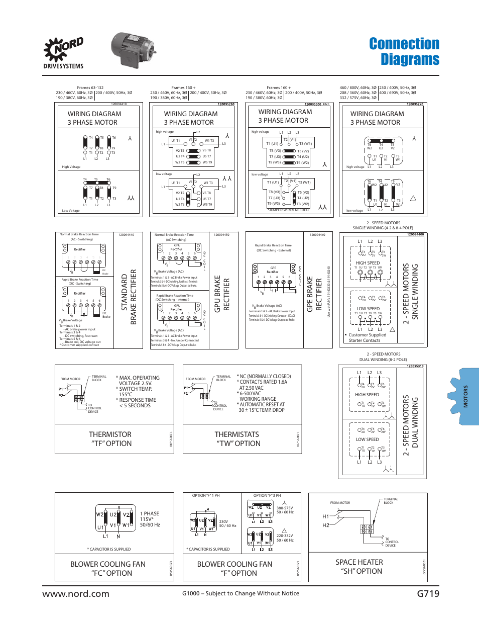
When it comes to working on electrical systems in brake motors, having a clear understanding of the wiring diagram is crucial. A Brake Motor Wiring Diagram is a detailed schematic that shows the various components and connections within the motor’s electrical system. By referring to this diagram, mechanics and technicians can easily identify and troubleshoot any issues that may arise.
Importance of Brake Motor Wiring Diagram
Brake Motor Wiring Diagrams are essential for several reasons:
- They provide a visual representation of the motor’s electrical system.
- They help in identifying the various components and their connections.
- They serve as a guide for proper installation and maintenance of the motor.
- They aid in troubleshooting electrical problems quickly and efficiently.
Reading and Interpreting Brake Motor Wiring Diagram
When looking at a Brake Motor Wiring Diagram, it’s essential to understand the symbols and notation used. Here are some key points to keep in mind:
- Identify the power source and ground connections.
- Understand the different components such as capacitors, switches, and relays.
- Follow the flow of current through the various circuits.
Using Brake Motor Wiring Diagram for Troubleshooting
Brake Motor Wiring Diagrams are invaluable tools for troubleshooting electrical problems. By following these steps, you can effectively diagnose and fix issues:
- Refer to the wiring diagram to identify the specific components involved in the problem.
- Check for loose connections, damaged wires, or faulty components.
- Use a multimeter to test continuity and voltage at various points in the circuit.
- Refer to the diagram to trace the flow of current and identify any abnormalities.
Safety Tips for Working with Brake Motor Wiring Diagram
When working with electrical systems and wiring diagrams, safety should always be a top priority. Here are some essential tips to keep in mind:
- Always disconnect the power source before working on the motor.
- Use insulated tools to prevent electrical shock.
- Double-check your connections before applying power to the motor.
- Wear appropriate personal protective equipment, such as gloves and safety goggles.
Brake Motor Wiring Diagram
Engine Brake Wiring Diagram – Wiring Diagram and Schematics

Clutch Brake Motor Connection Diagram Rectifier Module – YouTube

Motor brake rectifier connection diagram | Engineers CommonRoom

Engine Brake Wiring Diagram – Wiring Diagram and Schematics

brake motor wiring diagram
Nord Brake Motor Wiring Diagram – Coearth
