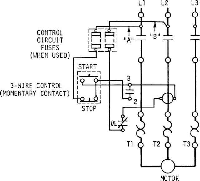
Basic Start Stop Wiring Diagram
A Basic Start Stop Wiring Diagram is a visual representation of how a start-stop circuit is wired. This type of diagram is essential for understanding the electrical connections and components involved in controlling the operation of a motor or other electrical device.
Importance of Basic Start Stop Wiring Diagram
- Helps in understanding the circuit layout and connections
- Aids in troubleshooting electrical issues
- Ensures proper installation and operation of the start-stop system
Reading and Interpreting Basic Start Stop Wiring Diagram
When interpreting a Basic Start Stop Wiring Diagram, it is important to pay attention to:
- The symbols used for different components such as switches, relays, and motors
- The direction of current flow indicated by arrows
- The connections between components and how they interact
Using Basic Start Stop Wiring Diagram for Troubleshooting
Basic Start Stop Wiring Diagrams can be invaluable for troubleshooting electrical problems. By following the diagram, you can:
- Identify faulty components or connections
- Trace the path of the electrical circuit to pinpoint the issue
- Compare the actual wiring with the diagram to find discrepancies
Importance of Safety
Working with electrical systems can be dangerous, so it is crucial to follow safety precautions when using wiring diagrams:
- Always turn off the power before working on any electrical circuit
- Use proper insulation and protective gear to prevent electric shocks
- Double-check all connections and wiring before energizing the circuit
Basic Start Stop Wiring Diagram
Start Stop Circuit – What They Are, Where They Are Used And How To Wire

The Essential Guide to Start-stop Diagram – RAYPCB

Start Stop Circuit Diagram
Basic Start Stop Circuit Diagram

Basic Start/Stop AC Motor Control Schematics under Repository-circuits

Start Stop Wiring Diagram
